F5 Distributed Cloud Services Site
Definition of a Site
A Customer Edge (CE) Site is a physical or cloud location where F5 nodes are deployed. A CE Site can be a public cloud location, like AWS, Azure, GCP VPC, physical data center, or an edge location, like a manufacturing site, factory, retail store, restaurant, charging stations, robots, and more. Even though F5® Distributed Cloud’s Regional Edges are available as Sites for F5 Distributed Cloud Mesh or F5 Distributed Cloud App Stack services, they are not marked in F5 Distributed Cloud Console (Console) or APIs as “customer sites”. Distributed Cloud Services can manage your CE sites for you and provides a common set of APIs to consume infrastructure, which allows your developers and DevOps teams to focus on their tooling and applications.
Cluster of Nodes
A CE Site is made up of a cluster of one or more nodes. The cluster can be scaled up or down by addition or deletion of nodes based on load. Each Node is a Linux-based software appliance (appliance is delivered as an ISO or deployment spec on K8s) that is deployed in a virtual machine, in a K8s cluster, commodity hardware, or F5 edge hardware. Kubernetes is used as the clustering technology and all the F5 Distributed Cloud software services run as K8s workloads in these clusters. In addition, customer workloads also run in this K8s cluster if App Stack services are enabled on these nodes. This managed K8s on node is referred to as “physical K8s” from now on.
A physical location may be deployed with multiple clusters of nodes, each individual cluster is considered as its own individual Site to ease manageability. As a result, an individual Site is a combination of location and cluster. If a physical CE Site has two clusters, then there are two sites in that location. Henceforward, a Site may be referred to as Site or location in the rest of the documentation.
Network Topology of a Site
You can deploy a CE Site using two modes:
- On a stick (single interface): In this case, the ingress and egress traffic from the node is handled on a single network interface as shown in the diagram. Inter-Site traffic goes over the IPsec tunnels (using the REs or optionally Site-to-Site). In this mode, the network functionality is delivered either by load balancer, gateway for Kubernetes, API proxy, a generic proxy, or application security functionality. Local network here refers to local data center network, VPC subnet in AWS, or VNET in Azure, or back-to-back network connection on a cluster of F5 Distributed Cloud hardware.
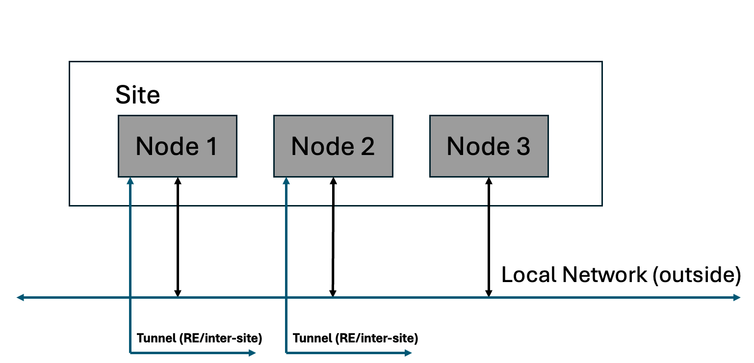
Figure: Site with Single Interface
- Default Gateway (two interfaces): In this case, there are two interfaces and the inter-Site traffic goes over IPsec tunnels that are connected over the local-network (outside). In this mode, as default gateway, the network functionality like routing and firewall between inside and outside networks can be enabled in addition to other application connectivity and security functionality. Local network here refers to local data center network, VPC subnet in AWS, or VNET in Azure, or back-to-back network connection on a cluster of F5 Distributed Cloud hardware.
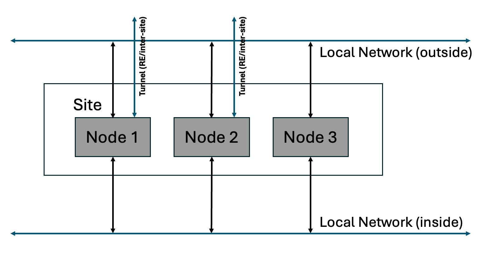
Figure: Site with Two Interfaces
Logical View of a Site
A node consists of many software components that provide computing, storage, network, and security services. A cluster comprised of multiple nodes, with its own physical K8s, acts as a super-converged infrastructure in use cases to run applications without the need for additional external components/software typically required by other systems.
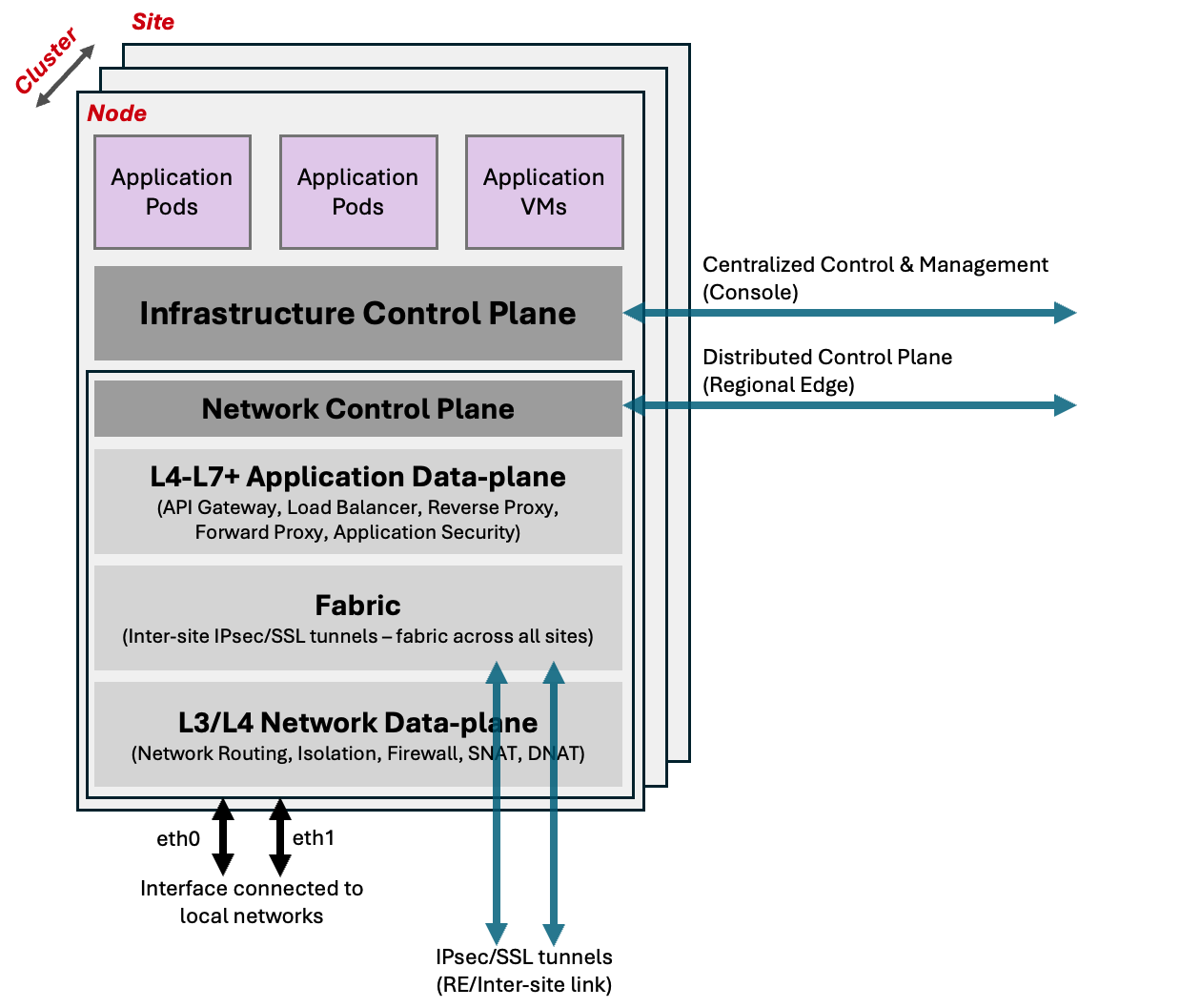
Figure: Logical View of Site
As each node comes up, it calls home to the F5 Distributed Cloud's centralized control and management plane. Once authenticated and approved by the user, it brings up Infrastructure Control Plane and forms a cluster of nodes (this includes the physical K8s). Once the control plane service is up and the cluster is formed, it starts deploying F5 Distributed Cloud microservices.
The infrastructure control plane, primarily composed of F5 Distributed Cloud's managed physical K8s, within the Site is responsible for the functioning and health of the nodes, F5 Distributed Cloud microservices, and your workloads running within the cluster. Once the registration is complete and the cluster is admitted into the F5 Distributed Cloud Service, the distributed control plane running in the Regional Edge Sites become responsible for launching and managing the workloads in the Site. This distributed control plane is also responsible for aggregating status, logs, metrics from individual Site and propagate it to the F5 Distributed Cloud Console (Console).
One of the microservices in the Site is the networking service that is responsible for all the Mesh services. It gets bootstrap config from a distributed control plane running in regional edges within the F5 Distributed Cloud global infrastructure. This service creates IPsec/SSL tunnels to regional edges (and/or inter-Site) that are configured during bootstrap of the node.
Using the secure tunnels, this service becomes part of the F5 Distributed Cloud Fabric, an isolated IP network, that helps it to connect to local control plane in regional edges or other Sites in the location. This fabric is also used for data plane traffic as underlay fabric. None of the physical interfaces can talk directly to this isolated fabric. Traffic on the fabric is going through a network firewall at every Site and only certain applications are allowed to communicate. It also has protections like reverse path forwarding checks to prevent any kind of spoofing, tenant level checks so that only Sites of same tenant can talk to each other.
Mesh network connectivity and security services includes following functions:
- IP switching/routing
- Isolated Networks for physical interfaces
- Isolated Networks for physical K8s namespace
- Connect networks directly or through source NAT (SNAT)
- Local internet breakout when used in default gateway mode
- Firewall policy - network (TCP, IP) security policy
- BGP routing to advertise VIPs within Site
Mesh application connectivity and security services includes the following functions:
- Application and API security policy
- Forward Proxy
- Load Balancer
- Application policy (based on HTTP, APIs, and more)
- API proxy
- Web Application firewall
Additionally, Regional Edge Sites can provide functionality for CE sites and applications:
- Expose applications on the public Internet and use the F5 global network for services, like anycast, global load balancing, application security, volumetric DDoS, and more
- Offload network and application connectivity and security services on regional edges
- Tunnel the CE Site to regional edges and use the F5 global network as your backbone network with complete DMZ functionality
Configuring a Site
Certified Hardware
One of our objectives is to help customers easily deploy and manage infrastructure in cloud or edge and make it part of their own “logical cloud” spanning multiple cloud providers and/or edge locations.
The initial deployment and admission control is done using zero touch provisioning (ZTP) to make the bring-up process easy and secure. As nodes can be deployed in multiple configurations across multiple platforms, it requires ZTP with multiple flavors of bootstrap configuration. Initial boot of the device needs to have enough configuration so that device can call home to centralized control plane. As a result, F5 bundles different bootstrap configurations in the node software image.
Certified hardware object represents physical hardware or a cloud instance that is used to instantiate the node in a given configuration for the Site. It has the following information for bootstrap:
- Type
- List of vendor model
- List of devices supported (for example, network interfaces)
- Image name
Certified hardware objects are only available in the shared namespace. These are created and managed by F5 Distributed Cloud Services and users are not allowed to configure this object. It lets users know of various hardware and cloud images that are supported, how they can be used, configured at bootstrap, and image name that needs to be downloaded to make the config work.
Details on all the parameters that can be configured for this object is covered in the API specification.
Site Registration
To register a Site, your tenant needs to allocate a token as part of the ZTP process. This token can be part of the ISO image that is downloaded for physical node or inserted into the VM as part of cloud init or given as part of deployment spec on launching on K8s. In the case of ISO, user can request token to be part of the image when downloading it from the Console.
When a node’s software boots up, it is expected to call home to register. In order for the call home to succeed, there has to be at least one interface up with connectivity to the centralized control and management service - this interface is defined in certified hardware and needs to be appropriately configured at bootstrap. During call home, a node sends a registration request with the token to identify the tenant and any additional information about the node. For example, that information includes certified hardware, hardware info, and more.
This new Site then shows up as a new registration request in the Console. User can approve or deny the registration request and optionally assign various parameters like Site name, geographic location, and labels.
When new nodes show up for registration, if they have the same Site name, then they automatically become part of the cluster after approval. An individual Site supports 2n+1 configuration for cluster’s control nodes - with a minimum of one control node. After three nodes, you can add any number of nodes and the rest become worker nodes. In a cloud environment, worker nodes can be automatically scaled without requiring additional registration. This can be based on load or manually changing the number in Site configuration.
This whole registration process can be automated with bulk registration and use of the TPM on physical hardware node to store crypto certificates and keys that identify the node, tenant, and more. This needs custom integration with your backend and new certified hardware instance and can be requested through the support channel.
On-a-stick Deployment (Single Interface)
If the Site is being deployed in the single interface (on a stick) mode, determined by the image selected and its configuration, the following things happen during the deployment process:
-
The single “physical” interface is assigned to be of type SITE_LOCAL_OUTSIDE by the system automatically, with DHCP enabled. Using DHCP, the node gets its IP address, subnet, default gateway, and DNS server configuration. Static IP configuration is planned for future releases.
-
This Interface is also configured to be part of a virtual network which is of type SITE_LOCAL_NETWORK. This information is relevant later for configuring additional features for the Site. For example, a network firewall.
-
IP address of this interface is called HOST_IP in SITE_LOCAL_NETWORK. This IP address is assigned to the interface. This information is relevant later when the system automatically selects VIP for this Site.
Default Gateway Deployment (Two or More Interfaces)
If the Site is being deployed in the default gateway (two interface) mode, determined by the image selected and its configuration, the following things happen during the deployment process:
-
The first interface is assigned to be of type SITE_LOCAL_OUTSIDE by the system automatically, with DHCP enabled. Using DHCP, the node gets its IP address, subnet, default gateway and DNS server configuration. Static IP configuration is planned for future releases.
-
This interface is also configured to be part of a virtual network which is assigned to be of type SITE_LOCAL_NETWORK. This information is relevant later for configuring additional features for the Site. For example, a network firewall.
-
Second interface is assigned to be of type SITE_LOCAL_INSIDE and usually does not have any configuration. User can enable DHCP or assign a static IP address to this interface.
-
This second interface is also configured to be part of a virtual network, which is assigned to be of type SITE_LOCAL_NETWORK_INSIDE. If DHCP server is configured for this network, this Site becomes default gateway for SITE_LOCAL_NETWORK_INSIDE network and assigns IP addresses to any client on the network.
-
IP address of both interfaces is called HOST_IP in their respective networks: SITE_LOCAL_NETWORK and SITE_LOCAL_NETWORK_INSIDE.
VIP for a Cluster of Multiple Nodes
As discussed earlier, the VIP is chosen from the interface HOST_IP. However, in the case of multiple nodes, there are multiple interface IPs. This may not be desired in many cases and to solve this problem, one can configure a common VIP on the inside and outside network in the Site object. Whenever there is a need to select VIPs automatically, this VIP is preferred over HOST_IP.
Details on all the parameters that can be configured for this object is covered in the API specification.
Site Connectivity to Regional Edge
When a Site is approved, the system automatically selects two regional edge Sites based on public IP address with which Site registration was received by the centralized control plane. In some scenarios, geo-IP database may not be accurate and users can override the selected regional edges and provide “ves.io/ves-io-region” label to explicitly provide RE preference. The system connects to two regional edges from this label and if they are not available, it connects to other nearby Sites in the region.
Once these REs are selected, the list of two selected regional edges is passed down to the Site as part of the registration approval. Also, the following additional information is sent as part of this approval:
- Site identity and PKI certificates: These certificates are regularly rotated by the system.
- Initial configuration to create and negotiated secure tunnels for the F5 Distributed Cloud fabric.
The Site tries to negotiate both IPsec and SSL tunnels to the selected RE sites. If the CE Site establishes IPsec connectivity, then IPsec is the preferred method. Otherwise, it resorts to SSL tunnels. Once the connectivity is established, the fabric comes up and the distributed control plane in the RE Site takes over the control of the Site. These tunnels are used for management, control, and data traffic. Site-to-Site traffic and Site-to-public traffic goes over these tunnels.
Site to Site Connectivity
In many cases, tenants may need to connect “Sites” that are located within the same location using their existing networks or “Sites” across locations using their own backbone network and not use the global network for the connectivity of Sites. Tenants that prefer to utilize their backbone should be able to send data traffic between Sites using their own network instead of F5 Distributed Cloud Services. This is achieved by creating Site-to-Site tunnels using a Site Mesh Group (SMG).
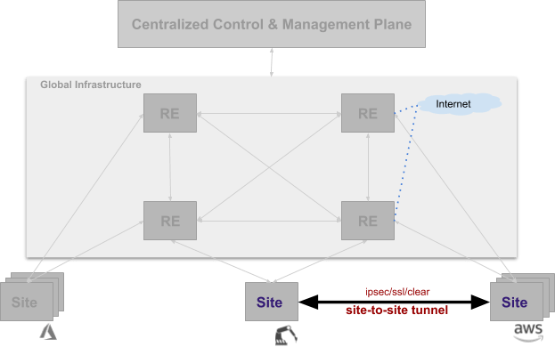
Figure: Connectivity Using Site Mesh Group
A Site Mesh Group is a configuration object that defines a group of arbitrary sites and sets up tunnels between those sites using IPsec. Clear/unencrypted tunnels are also possible using a DC Cluster Group (DCCG). If the Site Mesh Group is a hub, then all sites within this group form full mesh connectivity. If the Site Mesh Group is spoke, then it has corresponding hub Site Mesh Group. Each CE Site in a spoke group sets up tunnels with all Sites in a corresponding hub group.
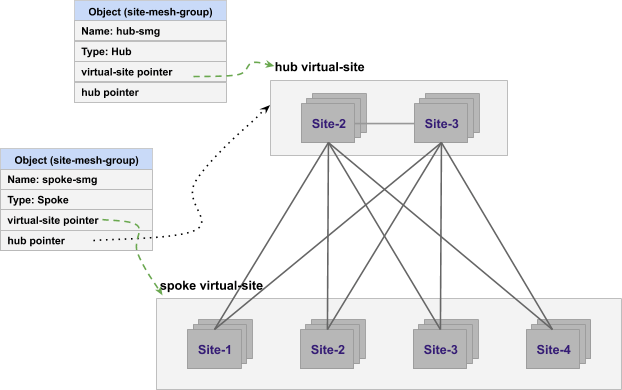
Figure: Hub and Spoke Combinations of Site Mesh Group
Details on all the parameters that can be configured for this object is covered in the API specification.
In case of IPsec connection between Site and Regional Edge or between two Sites, both Public Key Infrastructure (PKI) and Pre-Shared-Key (PSK) mode are supported. When using PKI, system supports RSA 2048 certificates to authenticate remote peers. The following ciphers are used:
- Key Exchange: aes256-aes192-aes128, aes256gcm16
- Authentication: sha256-sha384
- DH groups: ecp256-ecp384-ecp521-modp3072-modp4096-modp6144-modp8192
- ESP: aes256gcm16-aes256/sha256-sha384
Site - Local Internet Breakout
Even though the ideal point of egress traffic to the Internet is from the Regional Edge (RE) Site, it may be required to send some traffic directly to the internet. Also, please note that this discussion is only valid in the two interface (default gateway) mode.
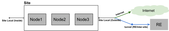
Figure: Site Local Network to Internet Connectivity
The virtual network on the inside (Site Local Inside) can be connected to the outside physical network (Site Local) using a network connector. On this network connector, you can configure SNAT, policy based routing, forward proxy for URL filtering, and network firewall.
Details on all the parameters that can be configured for this object is covered in the API specification.
Virtual Site
A virtual Site is a tool for indirection. Instead of doing configuration on each Site, it allows for performing a given configuration on set (or group) of Sites. Virtual Site is a configuration object that defines the Sites that members of the set.
A set of sites in the Virtual Site is defined by label expression. So you can have a Virtual Site of all sites that have “deployment in (production) and region in (sf-bay-area)”.
A Virtual Site object is used in an SMG, A Virtual Site is used in application deployment, advertise policy, or service discovery of endpoints. These label expressions can create intersecting subsets. Hence, a given Site is allowed to belong to many virtual sites.
Concept of “Where”
Technically an endpoint (for example, DNS server, K8s API or any such name to be resolved) should resolve finally to virtual network and IP address. Since it is not always convenient or even possible to provide a virtual network and an IP address, F5 provides the capability of defining “where” in many API(s). This concept of “where” makes it easier to perform configuration and policy definition upfront.
Value of “where” can be any one of the following:
- Virtual Site: configuration applied “where” all Sites selected by virtual Site and Site local network type on that Site. Name is resolved there or discovery is done on all these Sites.
- Virtual Site, network type: configuration applied to “where” all Sites selected by virtual Site and network type on those Sites.
- Site, network type: configuration is applied on this specific Site and virtual network of given type.
- Virtual network: configuration is applied to all Sites “where” this network is present.
Fleet
Typically, when you deploy many Sites, it is common to perform same configuration steps on each Site (using automation or manually) - for example configuration on physical constructs (on the Site) like interfaces, virtual networks, network firewalls, and more. In order to remove the need for performing configuration on each Site individually, F5 provides the capability to manage a set of sites as a group.
Since virtual-Site object allows an individual Site to belong to multiple virtual Sites, this object is not ideal for performing configuration on physical constructs like interfaces - as it can cause ambiguity problems if two virtual Site objects contain different configurations for a single physical entity.
To solve this disambiguation problem of configuration to physical constructs, F5 provides the capability to manage sites with “fleet” object. This set has to be exclusive, and the same site cannot be present in two “fleet” objects.
Configuring a Fleet
To configure a “fleet” object, you need to define a label on the object ves.io/fleet=<fleet label value>. Every fleet in a tenant has to have unique value of <fleet label value>. If this label is attached to Site, then the Site becomes part of that fleet. Label can be attached at the time of registration approval to get proper configuration for physical devices. A virtual Site representing this fleet is also created by the system automatically so that it can be used in other features where there is a need for virtual Site.
Fleet is also tied to certified hardware to map physical devices that are supported by the hardware. It has device-level configuration for each device - for example, interface configuration for each network device, firewall configuration for these Sites, USB configuration, I/O devices, storage devices, and more. Once the interfaces are defined as part of the fleet, then they become members of virtual network. Virtual networks may have connectors. In this way, a physical Site configuration can be done as fleet.
This means that one needs to always configure fleet when using features tied to fleet. This makes it easier to add additional members in the future without requiring changes to the initial Site. Fleet object, by assigning fleet label to Site, may be assigned to Site at the time of Site registration.
Details on all the parameters that can be configured for this object is covered in the API specification.
See Also
On this page:
- Definition of a Site
- Cluster of Nodes
- Network Topology of a Site
- Logical View of a Site
- Configuring a Site
- Certified Hardware
- Site Registration
- On-a-stick Deployment (Single Interface)
- Default Gateway Deployment (Two or More Interfaces)
- VIP for a Cluster of Multiple Nodes
- Site Connectivity to Regional Edge
- Site to Site Connectivity
- Site - Local Internet Breakout
- Virtual Site
- Concept of “Where”
- Fleet
- Configuring a Fleet
- See Also